Electrical Impedance
Characteristics: | KLIPPEL R&D System | KLIPPEL QC System |
|---|---|---|
Amplitude and phase response | LPM, TRF, MTON | IMP, SPL-IMP, MSC |
Impedance measured by using a large signal model
| MSC |
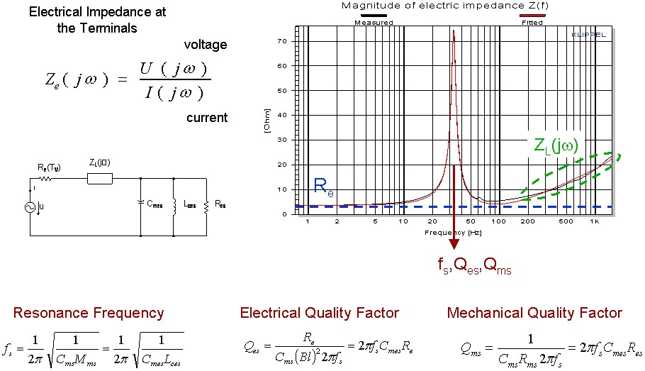
The electrical input impedance is defined as transfer function Z(jω)= U(jω)/ I(jω) between the electrical signals at the terminals in the small signal domain where the transducer behaves sufficiently linear. The impedance is the basis for estimating the linear parameters (Thiele-Small parameters, lossy inductance parameters, visco-elastic parameters) of the lumped parameter model. The minimum of the impedance above the fundamental resonance is used for defining the nominal impedance of the speaker. The conventional measurement of the impedance requires a measurement in the small signal domain where the nonlinear distortion in voltage and current are negligible. Large signal measurement requires a nonlinear model of the speaker where the effect of the nonlinear distortion can be compensated and the linear impedance can be calculated.


KLIPPEL R&D SYSTEM (development)
Module | Comment |
|---|---|
TRF measures magnitude and phase response of the electrical impedance by using a sinusoidal sweep stimulus. | |
LPM measures magnitude and phase response of the electrical impedance by using a multi-tone stimulus which ensures best SNR of voltage and current in the small signal domain. No smoothing of the curve is required. | |
| Multi-Tone Measurement (MTON) | MTON measures magnitude of the electrical impedance by using a multi-tone stimulus. Phase is available if transfer function is defined between voltage and current measurements.
|
KLIPPEL QC SYSTEM (end-of-line testing)
Module | Comment |
|---|---|
| The IMP measure the magnitude and phase response of the electrical impedance at high speed using a sinusoidal sweep (chirp) with amplitude and sweep speed profile or using a multi-tone stimulus. The measurement has to be performed in the small signal domain where the effect of the transducer nonlinearities is negligible. |
| Sound Pressure and Impedance Task (SPL-IMP) | The SPL-IMP measures the magnitude and phase response of the electrical impedance at high speed using a sinusoidal sweep (chirp) with amplitude and sweep speed profile. Limits can be applied. |
MSC measures the magnitude and phase response of the impedance also at high amplitudes by using an ultra-short multi-tone stimulus. The nonlinear distortion in the voltage and current are compensated by using the nonlinear parameters of the identified large signal transducer model.
|
Example:
Templates of KLIPPEL products
Name of the Template | Application |
|---|---|
LPM Microspeaker T/S (SP2) | Linear parameters of microspeakers using sensitive current sensor 2 |
LPM Subwoofer T/S (Sp1) | Linear parameters of subwoofers using standard current sensor 1 |
LPM Subwoofer T/S (Sp2) | Linear parameters of subwoofers using sensitive current sensor 2 |
LPM Tweeter T/S (SP2) | Linear parameters of tweeters using sensitive current sensor 2 |
LPM Woofer T/S (Sp1) | Linear parameters of woofers using standard current sensor 1 |
LPM Woofer T/S (Sp2) | Linear parameters of woofers using sensitive current sensor 2 |
LPM Woofer T/S added mass | Linear parameters of woofers using added mass method |
TRF Elect. Impedance (Sp 1) | Electrical impedance using the standard current sensor 1 |
TRF Elect. Impedance (Sp 2) | Electrical impedance using the sensitive current sensor 2 |
Diagnost. MIDRANGE Sp1 | Comprehensive testing of midrange drivers with a resonance 30 Hz < fs < 200 Hz using standard current sensor 1 |
Diagnost. SUBWOOFER (Sp1) | Comprehensive testing of subwoofers with a resonance 10 Hz < fs < 70 Hz using standard current sensor 1 |
Diagnostics MICROSPEAKER Sp2 | Comprehensive testing of microspeakers with a resonance 100 Hz < fs < 2 kHz using sensitive current sensor 2 |
Diagnostics TWEETER (Sp2) | Comprehensive testing of tweeters with a resonance 100 Hz < fs < 2 kHz using sensitive current sensor 2 |
Diagnostics VENTED BOX SP1 | Comprehensive testing of vented box systems using standard current sensor 1 |
Diagnostics WOOFER (Sp1) | Comprehensive testing of subwoofers with a resonance 30 Hz < fs < 200 Hz using standard current sensor 1 |
Diagnostics WOOFER Sp1,2 | Comprehensive testing of subwoofers with a resonance 30 Hz < fs < 200 Hz using current sensor 1 and 2 |
Application Notes
Standards
Audio Engineering Society
AES2 Recommended practice Specification of Loudspeaker Components Used in Professional Audio and Sound Reinforcement
International Electrotechnical Commission
IEC 60268-5 Sound System Equipment, Part 5: Loudspeakers
IEC 62458 Sound System Equipment – Electroacoustic Transducers - Measurement of Large Signal Parameters
Other Related Tests
Typical Test Objects
Papers and Preprints
W. Klippel, U. Seidel, “Fast and Accurate Measurement of Linear Transducer Parameters,” presented at the 110th Convention of the Audio Eng. Soc., Amsterdam, May 12-15, 2001, Preprint 5308, J. of Audio Eng. Soc., Volume 49, No. 6, 2001 June, P. 526. (abstract)
J. Vanderkooy, “A Model of Loudspeaker Driver Impedance Incorporating Eddy Currents in the Pole Structure,” J. of Audio Eng. Soc., Volume 37, No. 3, pp. 119-128, March 1989.
W. M. Leach, “Loudspeaker Voice-Coil Inductance Losses: Circuit Models, Parameter Estimation, and Effect on Frequency Response,“ J. of Audio Eng. Soc., Volume 50, No. 6, pp. 442-450, June 2002.
J. R. Wright, “An Empirical Model for Loudspeaker Motor Impedance,“ J. of Audio Eng. Soc., Volume 38, No. 10, pp. 749-754, October 1990.
M. Dodd, et al., “Voice Coil Impedance as a Function of Frequency and Displacement,” presented at the 117th Convention of the Audio Eng. Soc., 2004 October 28–31, San Francisco, CA, USA.
D. Clark, “Precision Measurement of Loudspeaker Parameters,“ J. of Audio Eng. Soc., Volume 45, pp. 129 – 140, (1997 March).
R. H. Small, “Direct-Radiator Loudspeaker System Analysis,“ J. of Audio Eng. Soc., Volume 20, pp. 383 – 395 (1972 June).