Research Electro-Acoustics
Schwerpunkte im elektrischen System
- Modellierung des elektrodynamischen und elektromagnetischen Wandlers im Großsignalbereich
- Identifikation der nichtlinearen Schwingspuleninduktivität als Funktion des Stromes und der Auslenkung
- Modellierung der nichtlinearen Wirbelstromverluste als Funktion des Stromes und der Auslenkung
- Dynamische Messung des nichtlinearen Koppelfaktors
- Messtechnische Bestimmung und Bewertung der Felddichte B im Magnetspalt
- Modellierung des Wärmeflusses im Lautsprecher und Schätzung der Erwärmung der Schwingspule durch das Eingangssignal unter Berücksichtigung von Wirbelströmen, Wärmeleitung und nichtlineare Konvektionskühlung,
- Identifikation der thermischen Parameter des Wandlermodelles auf Grundlage elektrischer Messdaten
- Modellierung des nichtlinearen Übertragungsverhaltens im Analog-Digitalkonverter (DAC) und Digital-Analogkonverters (ADC) und Identifikation der Volterra-Kernel
The electrical system - main areas of research
- Modelling of electro-dynamic and electro-magnetic transducers in the large signal domain
- Identification of the nonlinear voice coil inductance as function of current and displacement
- Modelling of the nonlinear losses generated by eddy currents as function of input current i and displacement
- Dynamic measurement of nonlinear coupling factor
- Scanning and assessing the homogeneity of the induction B in the magnetic gap
- Modelling of the thermal flow in the transducer and estimation of voice coil heating by input signal considering eddy currents, thermal conduction and nonlinear convection cooling.
- Identification of thermal parameters of the transducer model based on electric measurement data
- Modelling of the nonlinear transfer behaviour of analog-digital converter (DAC) and digital-analog converter (ADC) and the identification of the Volterra- Kernels
Beispiel: Modellierung der Nichtlinearitäten in Lautsprechern
Schallsender (z.B. Lautsprecher, Kopfhörer) können nur im Kleinsignalbereich als lineares System beschrieben werden. Bei größeren Amplituden verursachen Nichtlinearitäten im elektrodynamischen Wandler, in der mechanischen Aufhängung und in der Membran hörbare Signalverzerrungen und begrenzen das akustische Ausgangssignal. Das Großsignalverhalten nimmt zunehmend an Bedeutung zu bei vielen Anwendungen sowohl im Konsumerbereich (Auto, PC, Handy, ...) als auch bei der professionellen Beschallung, da hier kleine, leichte und kostengünstige Schallsender benötigt werden, die den erforderlichen Schalldruck mit hohem Wirkungsgrad in der erforderlichen Qualität erzeugen.
Auf Anregung von Prof. Kraak und Prof. Wöhle begann Wolfgang Klippel bereits 1987 an diesem Institut der TU Dresden mit der Entwicklung von nichtlinearen Modellen für elektroakustische Wandler, deren Parameter mit modernen Methoden der Systemidentifikation bestimmt werden können.
Example: Modelling of transducer nonlinearities
Sound sources (e.g. loudspeakers, headphones, actuators) can only be described as linear systems in the small signal domain. With higher amplitudes, nonlinearities cause audible signal distortion and limit the acoustical output signal in electro-dynamical transducers, in the mechanical suspension as well as in radiators (e.g. cone, membrane). The large signal behaviour gains more and more importance as small, light and cost effective transducers are needed in consumer applications (automotive, PC, mobile phones…) and in professional audio to create the necessary sound pressure taking quality and efficiency into account.
In 1987 and at the suggestion of Prof. Kraak and Prof. Wöhle, W. Klippel has started developing nonlinear models of electro-acoustical transducer which parameters can be defined by modern system identification techniques.
Elektrodynamischer Koppelfaktor Bl(x) als Funktion der Auslenkung x
Die linke Abbildung zeigt beispielsweise ein vereinfachtes Schnittbild eines elektrodynamischen Lautsprechers, in dem die Schwingspule (gelb) in ihrer Ruhelage (x=0) und das magnetische Feld im Spalt (schwarz) hervorgehoben sind. Bewegt sich die Schwingspule aus dem Spalt wird der elektrodynamische Koppelfaktor Bl, als Integral der von Leiter mit der Länge l durchflossenen magnetischen Flussdichte B, tendenziell weniger. Das rechte Diagramm zeigt die sich ergebende nichtlineare Abhängigkeit des Koppelfaktors Bl(x) von der Auslenkung der Schwingspule. Die Kurve zeigt eine suboptimale Positionierung der Schwingspule im Spalt, durch Verschiebung der Ruheposition um 2 mm in positive Richtung kann der Koppelfaktor Bl(x=0) im Kleinsignalbereich erhöht und die Kurve symmetriert werden. Das führt zu einer Erhöhung des Schalldruckes und zu geringen Verzerrungen im Ausgangssignal.
Electro-dynamic coupling factor Bl(x) as function of displacement x
The left image shows a simplified sectional view of an electro-dynamical transducer by highlighting the voice coil (yellow) at the rest position (x=0) and the magnetic field in the gap (black). If the windings of the voice coil leave the gap the electro-dynamic coupling factor BL which is the integral of the induction B over the wire lenght I becomes smaller. The right chart shows the resulting nonlinear dependency of the coupling factor Bl(x) on the voice coil displacement. The curve shows a suboptimal position of the voice coil in the gap. By moving the rest positon by 2mm towards the posivitve direction the coupling factor BL (x=0= in the small signal domain coan be increased and the curve balanced. This leads to an increase of the sound pressure and less distortion in the output signal.

Schwerpunkte im mechanischen System
- Modellierung des Schwingungsverhaltens von mechanischen Systemen mit konzentrierten und verteilten Parametern (FEA)
- Schwingungsmessung mit Hilfe optischer Laserabtastung
- Dynamische Identifikation der nichtlinearen und visko-elastischen Eigenschaften der mechanischen Aufhängung (Sicke, Zentrierung)
- Zerlegung der Membranschwingung in orthogonale Komponenten (Modalanalyse)
- Modellierung der Schaukelschwingungen (rocking modes) und Erkennung der Ursachen (unsymmetrische Massen und Steifigkeitsverteilung)
- Modellierung des durch nichtlineare Partialschwingungen und die Erzeugung von Signalverzerrungen
- Schätzung optimaler Materialparameter (komplexer E-Modul) der Komponenten (z.B. Membran, Sicke, Staubkalotte)
- Modellierung der zeitvarianten Parameterveränderung durch Belastung, Ermüdung Alterung, Klima
The mechanical system - main areas of research
- Modelling of the voice coil behavior of mechanical systems with lumped and distributed parameters (FEA)
- Optical measurement of surface vibration by laser scanning
- Dynamic identification of nonlinear and visco-elastic properties of the mechanic suspension (surround + spider)
- Decomposition of the total surface vibration into orthogonal components (modal analysis)
- Modelling of rocking modes and root cause analysis (unbalanced distribution of stiffness, mass, Bl)
- Modelling of nonlinear cone vibrationand generated signal distortion
- Estimation of optimal material parameter (complex E-module) of soft parts (e. g. membrane, dust cap, surround)
- Modelling of time-variance of transducer parameters due to load, fatigue, ageing, climate
Beispiel: Messung des Schwingungsverhaltens von Membranen
Neben der Messung elektrischer Signalen an den Lautsprecherklemmen und des akustischen Ausgangssignals gewinnt die direkte Messung von mechanischen Zustandsgrößen zunehmende Bedeutung für die Lautsprecherentwicklung. Mit Hilfe von Laserscannern kann die Auslenkung der gesamten Membranfläche in relativer kurzer Zeit berührungslos gemessen werden. Mit Hilfe dieser mechanischen Schwingungsdaten und der gleichzeitig gemessenen Geometrie des Schallstrahlers kann das akustische Ausgangssignal an einen beliebigen Punkt im Schallfeld berechnet werden. Die enge Verbindung von Messtechnik und numerischer Simulation (FEM, BEM) erleichtert die Diagnose und Lokalisierung von Problemen, die entweder ihre Ursache im mechanischen Schwingungsverhalten oder in der akustischen Abstrahlung haben.
Die mechanischen Schwingungsdaten sind die Grundlage für die Modalanalyse und für eine schalldruckbezogene Zerlegungsmethode, die den konstruktiven bzw. destruktiven Beitrag jeder Schwingungskomponente zum Schalldruck im Schallfeld zeigt.
Example: Measurement of vibration behaviour of membranes
Beside the measurement of electrical signals at the transducer terminals and the measurement of the acoustic output signal, the direct measurement of mechanical properties gains more and more importance in the transducer development. The displacement and the geometry of radiator’s surface can be measured contactless by laser scanning within a short period of time. Based on this information the sound pressure can be calculated at any point in the sound field. The close relationship between measurement technique and numeric simulation (FEM, BEM) facilitates the diagnosis and localisation of problems originating either from the mechanical vibration behaviour or from the acoustical radiationl. The mechanical vibration data is the basis of the modal analysis and of the sound pressure related analysis method, showing the constructive and destructive input of each vibration component to the sound pressure in the sound field.
Schwerpunkte im akustischen System
- Modellierung akustischer Systeme mit Hilfe konzentrierter und verteilter Parameter (FEA)
- Berechnung und Optimierung der Schallabstrahlung bei Lautsprechern (BEA)
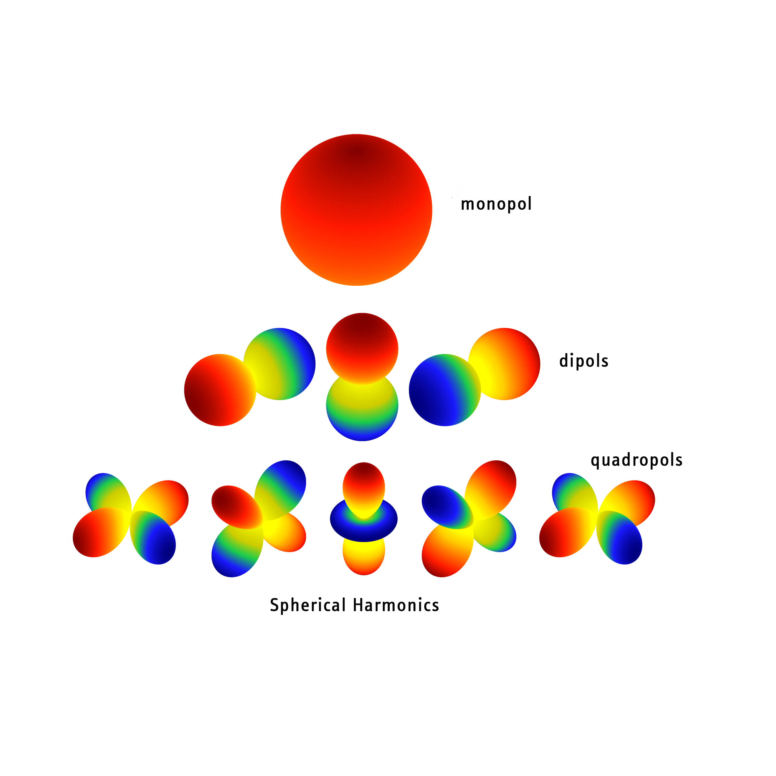
- Vollständige Beschreibung des vom Lautsprecher abgestrahlten Direktschalles im 3D Raum mit Hilfe von Kugelwellenentwicklungen (Fourier Akustik)
- Separierung des Direktschalles, Raumreflexionen und des am Lautsprechergehäuse gebeugten Sekundärschalles
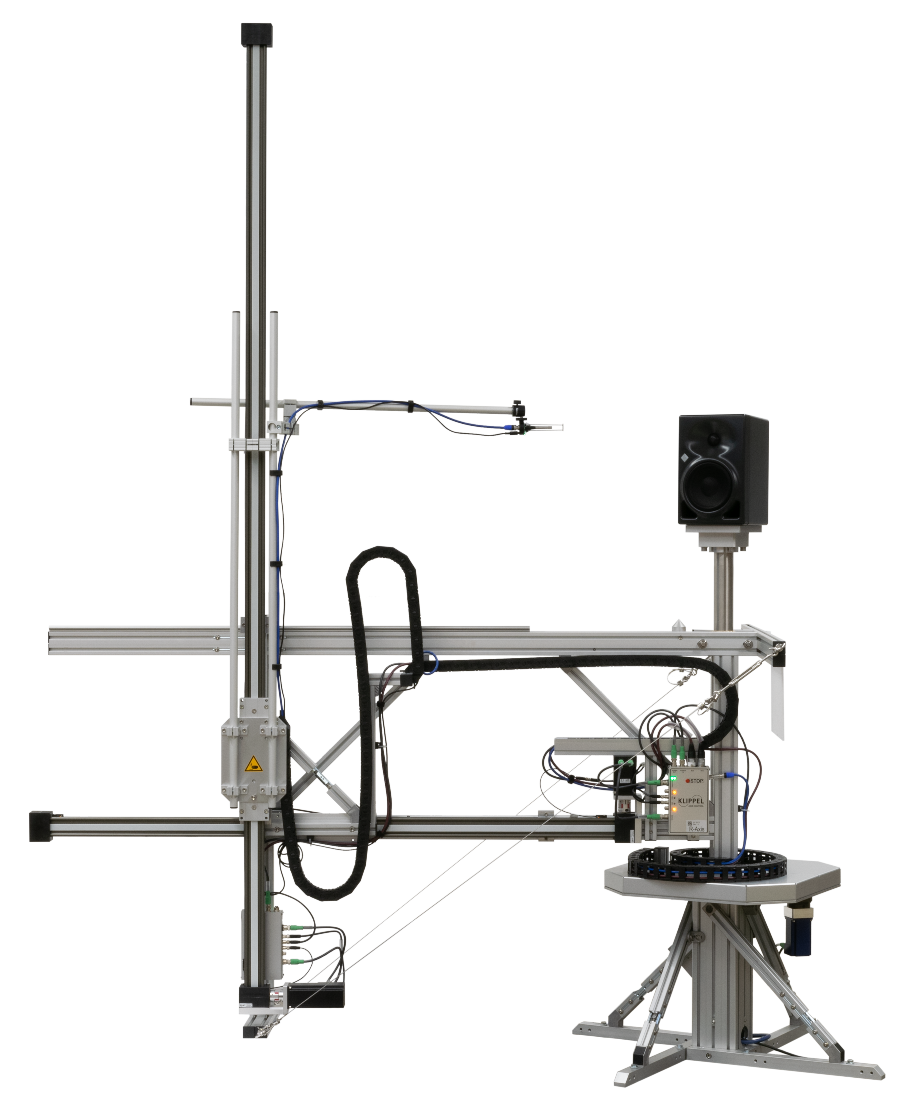
- Akustische Nahfeldholographie zur Messung des vom Schallsender erzeugten Direktschalles an einem beliebigen Punkt im 3D Raum außerhalb der Abtastfläche
- Modellierung der dominanten akustischen Nichtlinearitäten (adiabatische Kompression, Wellenaufteilung, Luftströmung) und Identifikation der nichtlinearen Modellparameter
The acoustic system: main areas of research
- Modelling of acoustic systems with lumped and distributed parameters (FEA)
- Calculation and optimization of the sound radiation of transducers (BEA)
- Complete description of the direct sound radiated by the transducer in a 3D room with the help of spherical waves (Fourier acoustic)
- Separation of the direct sound, the room reflexion and the secondary sound generated at the transducer enclosure by diffraction
- Acoustic near-field holography for measuring the direct sound generated by the sound source at any point in the 3D room beyond the scanning field
- Modelling of the dominant acoustical nonlinearities (adiabatic compression, wave distribution, air flow) and identification of the nonlinear model parameters
Beispiel: Holografische Messung des vom Lautsprecher erzeugten Direktschalles
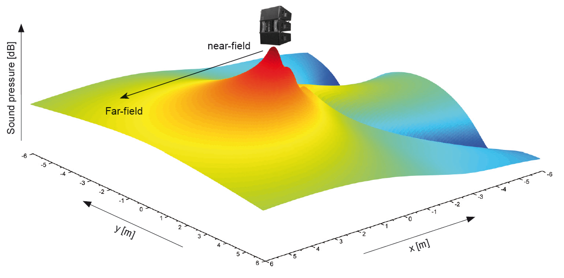
Lautsprecher werden in der Regel nur mit einem Eingangssignal gespeist, erzeugen jedoch ein unterschiedliches Ausgangssignal an jedem Punkt des Schallfeldes. Die vollständige Erfassung des abstrahlten Schallfeldes ist mit einer holografischen Messung möglich. Hierbei wird das Nahfeld des Lautsprechers mit einem Mikrofonscanner auf zwei den Lautsprecher eng umschließenden Hüllflächen abgetastet und der Schalldruck an allen Messpunkten mit einer Kugelwelle (sphärische Harmonische und Hankelfunktionen) beschrieben, die Lösungen der Differentialgleichung für eine konzentrierte Schallquelle im freien Schallfeld darstellen. Mit dieser Reihenentwicklung kann der Schalldruck an einem beliebigen Punkt außerhalb der Abtastfläche berechnet werden. Die Richtcharakteristik und andere Daten im Fernfeld (r>>d) sind für die Lösung professioneller Beschallungsaufgaben erforderlich. Die Bewertung und Optimierung von Smartphone, Notebooks und anderen persönlichen Audiogeräten erfordern den Schalldruck im Nahfeld des Schallsenders.
Example: Holographic measurement of the direct sound generated by the transducer
Usually, transducers are supplied with one input signal only. However, they create a different output signal at every point of the sound field (SIMO-System). The radiated sound field in the 3D space can be completely captured by using a holographic measurement technique. The sound pressure is measured in the nearfield of the transducer on two surfaces by using a microphone moving over the scanning points by robotics. The scanning data are described by spherical wave expansion (spherical harmonics and Hankel function), which are solutions of the differential equation for a sound source under free field condition. Based on this wave expansion the sound pressure can be calculated at any point beyond the scanning surface. The directivity as well as other data of the far field (r>>d) are important for professional sound applications. The assessment and optimization of smart phones, note books and other personal audio devices require the sound pressure in the near field of the transducer.