Waveform and Spectrum
Characteristics: | KLIPPEL R&D System | KLIPPEL QC System |
|---|---|---|
| Time domain analysis | LSI3, LPM, TRF, DIS, PWT, SIM-AUR, SCN, MTON, TBM | QC Standard |
| Statistical analysis | LSI3, LPM, TRF, DIS, PWT, SIM-AUR, SCN, MTON | QC Standard |
| Spectral analysis | LPM, TRF, DIS, MTON, TBM | QC Standard |
| Signal to noise ratio SNR | LPM, TRF, DIS, SCN |

Many modules of the KLIPPEL R&D SYSTEM measure important characteristics of the signal measured by using a sensor or predicted by using a loudspeaker model. Those characteristics can be monitored over time and stored in a history using a stand-alone hardware or a PC.
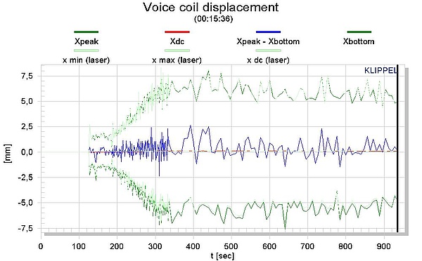
The rms value is important for calculating power and efficiency but also for assessing the heat dissipation. The peak value is very important for monitoring the voltage at the loudspeaker terminals and for defining the amplifier requirements. The measurement of the negative and positive peak value of the voice coil displacement and its difference is important for explaining nonlinear rectification mechanisms generated by asymmetrical nonlinearities.
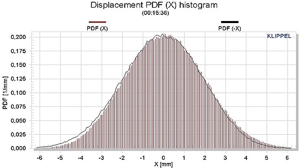
The crest factor and the probability density function are very useful to describe the audio signals and complex test signals (noise, multi-tone signal). The signal to noise ratio SNR is also a simple and important measure describing the noise immunity of the signal. A spectral analysis applied to the primary measurement signals reveals humming components and other disturbances and the SNR at critical frequencies (for example at very low frequencies).
KLIPPEL R&D SYSTEM (development)
Module | Comment |
|---|---|
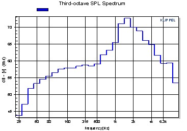
TRF always shows waveform, spectrum and other single-valued characteristics of the measured signals. A spectral analyzer mode repeats the measurement and calculates the magnitude in octave and third-octave band. Noise floor monitoring reveals the SNR. | |
LPM reveals all relevant properties of the signals (voltage, current, displacement and sound pressure) used for Linear Parameter Measurement and multi-tone distortion measurements. It separates noise from distortion to find the optimal voltage required for doing reliable measurements in the small signal domain. | |
LSI3 monitors the signal properties of voltage and current signals and the internal states (displacement, velocity, distortion in sound pressure output) during the large signal measurement using the internal noise stimulus. | |
PWT measures the signal properties of the arbitrary stimulus (test signal from internal generator or external audio signal) and the state variables of the transducer (e.g. displacement). | |
DIS module monitors the signal properties of the two-tone stimulus and of the measured signals. | |
SCN displays the spectrum and waveform of the measured displacement during the scanning process. | |
SIM-AUR analyzes the signal properties of the audio input signal at the loudspeaker terminals, the internal states (displacement, velocity) and the acoustical output signal. | |
SIM module predicts the state variables and acoustical output signal of loudspeaker systems based on a large signal model and parameters. Spectral and time domain analysis is applied to the different signals. | |
| Multi-Tone Measurement (MTON) | MTON monitors the signal properties of the multi-tone stimulus and the measured signals (voltage, current, displacement and sound pressure). It calculates the multi-tone distortion of the measured signals as well as the statistical information as the PDF, the crest factor or the kurtosis of the stimulus. |
| Tone Burst Measurement (TBM) | TBM module monitors the properties of the measured signals (voltage, current, displacement and sound pressure) using tone burst signals as stimuli. |
KLIPPEL QC SYSTEM (end-of-line testing)
Module | Comment |
|---|---|
All modules and tasks of the QC SYSTEM provide a summary on the signal properties, including rms, peak and headroom in the ADC and DAC. For most measures spectra in definable resolution are provided. A special tool called “Signal Test” provides analysis and export of waveform and spectra of any user selectable input. It is included in all QC System versions. |
Templates of KLIPPEL Products
Name of the Template | Application |
|---|---|
TRF 3rd oct. spectr. analyzer | Continuous loop measurement giving the spectrum of the signal acquired via IN1 integrated over 1/3 octave |
Diagnost. MIDRANGE Sp1 | Comprehensive testing of midrange drivers with a resonance 30 Hz < fs < 200 Hz using standard current sensor 1 |
Diagnost. RUB&BUZZ Sp1 | Batch of Rub & Buzz tests with increased voltage (applied to high power devices) |
Diagnost. RUB & BUZZ Sp2 | Batch of Rub & Buzz tests with increased voltage (applied to low power devices) |
Diagnost. SUBWOOFER (Sp1) | Comprehensive testing of subwoofers with a resonance 10 Hz < fs < 70 Hz using standard current sensor 1 |
Diagnostics MICROSPEAKER Sp2 | Comprehensive testing of microspeakers with a resonance 100 Hz < fs < 2 kHz using sensitive current sensor 2 |
Diagnostics TWEETER (Sp2) | Comprehensive testing of tweeters with a resonance 100 Hz < fs < 2 kHz using sensitive current sensor 2 |
Diagnostics VENTED BOX SP1 | Comprehensive testing of vented box systems using standard current sensor 1 |
Diagnostics WOOFER (Sp1) | Comprehensive testing of subwoofers with a resonance 30 Hz < fs < 200 Hz using standard current sensor 1 |
Diagnostics WOOFER Sp1,2 | Comprehensive testing of subwoofers with a resonance 30 Hz < fs < 200 Hz using current sensor 1 and 2 |
IEC 20.6 Mean SPL | Mean sound pressure level in a stated frequency band according IEC 60268-5 chapter 20.6 |
IEC 21.2 Frequency Range | Effective frequency range according to IEC 60268-5 chapter 21.2 |
IEC 22.4 Mean Efficiency | Mean efficiency in a frequency band according to IEC 60268-5 chapter 22.4 |
LSI Tweeter Nonlin. Para Sp2 | Tweeters with fs > 400 Hz at sensitive current sensor 2 |
LSI Headphone Nonlin. P. Sp2 | Nonlinear parameters of headphones with fs < 300 Hz at sensitive current sensor 2 |
LSI Woofer Nonl. P. Sp1 | Nonlinear parameters of woofers with fs < 300 Hz at standard current sensor 1 |
LSI Woofer Nonl.+Therm. Sp1 | Nonlinear and thermal parameters of woofers with fs < 300 Hz at standard current sensor Sp1 |
LSI Woofer+Box Nonl. P Sp1 | Nonlinear parameters of woofers operated in free air, sealed or vented enclosure with a resonance frequency fs < 300 Hz at standard current sensor Sp1 |
LSI Microspeaker Nonl. P. Sp2 | Nonlinear parameters of microspeakers with fs > 300 Hz at sensitive current sensor 2 |
LPM multitone distortion SP1 | Multi-tone distortion at high amplitudes (see Application Note AN 16) using standard current sensor 1 |
LPM Microspeaker T/S (SP2) | Linear parameters of microspeakers using sensitive current sensor 2 |
LPM Subwoofer T/S (Sp1) | Linear parameters of subwoofers using standard current sensor 1 |
LPM Subwoofer T/S (Sp2) | Linear parameters of subwoofers using sensitive current sensor 2 |
LPM Tweeter T/S (SP2) | Linear parameters of tweeters using sensitive current sensor 2 |
LPM Woofer T/S (Sp1) | Linear parameters of woofers using standard current sensor 1 |
LPM Woofer T/S (Sp2) | Linear parameters of woofers using sensitive current sensor 2 |
LPM Woofer T/S added mass | Linear parameters of woofers using added mass method |
TRF cumulative decay | Cumulative spectral decay |
TRF Elect. Impedance (Sp 1) | Electrical impedance using the standard current sensor 1 |
TRF Elect. Impedance (Sp 2) | Electrical impedance using the sensitive current sensor 2 |
TRF Harmonics current (Sp1) | Harmonics of the current signal using standard sensor 1 |
TRF Peak harmonics, time domain | Peak value of higher-order harmonics in time domain for Rub & Buzz analysis |
TRF rubb+buzz w/o Golden Unit | Rub & Buzz detection without "Golden Unit" according Application Note AN 22 |
TRF rubb+buzz with Golden Unit | Rub & Buzz detection with "Golden Unit" according Application Note AN 23 |
TRF sensitivity (Mic 2) | Calibration of the microphone at IN2 using a pistonphone |
TRF SPL + harmonics | Standard measurement for fundamental component (SPL) and harmonic distortion |
TRF SPL + waterfall | Sound pressure level and cumulative decay spectrum |
TRF true acoustical phase | Total phase without time delay |
DIS 3D Harmonics AN 9 | Harmonic distortions versus frequency and voltage according to Application Note AN 9 |
DIS 3D Intermodulation AN8 | Intermodulation distortions versus frequency and voltage according Application Note AN 8 |
DIS Compression Out(in) | Output amplitude versus input amplitude at four frequencies |
DIS Harmonics vs. Voltage | Harmonic distortion measurement versus amplitude |
DIS HI-2 | Weighted harmonic distortion (blat distortion) used for Application Note AN 7 |
DIS IM Dist. (bass sweep) | Intermodulation distortion in current and sound pressure using a variable bass tone fs/4 < f1 < 4fs and a fixed voice tone f2 >> fs |
DIS IM Dist. (voice sweep) | Intermodulation distortion in current and sound pressure by using a fixed bass tone f2 < fs and a variable voice tone f1>> fs |
DIS Motor stability | Checking motor stability at frequency 1.5 fs (where Xdc is maximal) according Application Note AN 14 |
DIS SPL, Harm protected | Harmonic distortion measurement with protection |
DIS X Fundamental, DC | Fundamental and DC component of displacement |
DIS Separation AM Distortion | Amplitude modulation distortion according Application Note AN 10 |
SIM closed box analysis | Maximal displacement, dc displacement, compression, SPL, distortion using large signal parameters imported from LSI BOX |
SIM Compression Out(In) | Output amplitude versus input amplitude at four frequencies using large signal parameters imported from LSI; Simulated results are comparable with DIS Compression Out(In). |
SIM Equiv. Input Harmonics | Equivalent input harmonic distortion using large signal parameters imported from LSI; Simulated results are comparable with TRF Equiv. Input Harm. (SPL). |
SIM IM Dist. (bass sweep) | Intermodulation distortion in current and sound pressure by using a variable bass tone fs/4 < f1 < 4fs and a fixed voice tone f2 >> fs; Simulated results are comparable with DIS IM Dist. (bass sweep). |
SIM IM Dist. (voice sweep) | Intermodulation distortion in current and sound pressure by using a fixed bass tone f2 < fs and a variable voice tone f1>> fs; Simulated results are comparable with DIS IM Dist. (voice sweep). |
SIM Motor Stability | Checking motor stability according Application Note AN 14; Simulated results are comparable with DIS Motor stability. |
SIM Therm. Analysis (1 tone) | Heat transfer based on thermal parameters imported from LSI using a single-tone stimulus |
SIM Therm. Analysis (2 tone) | Heat transfer based on thermal parameters imported from LSI using a two-tone stimulus |
SIM vented box analysis | Maximal displacement, dc displacement, compression, SPL, harmonic distortion using large signal parameters imported from LSI BOX |
SIM X Fundamental, DC | Maximal displacement, dc displacement, compression using large signal parameters imported from LSI; Results are comparable with DIS X Fundamental, DC. |
SIM Separation AM Distortion | Amplitude modulation distortion according Application Note AN 10; Simulated results are comparable with DIS Separation AM Distortion. |
MAT Add curve (dB) | Adding the sound pressure of two curves given in 'dB'; The weighting is applied to the sound pressure. |
MAT FreqTranslate | Transformation of the frequency axis |
MAT Sub curve (dB) | Subtracts "CurveB" weighted with "weightB" from "CurveA" weighted with "weightA" using curves in various formats (real, complex, dB + phase) |
CAL Add curves | Adds "CurveA" weighted with "weightA" to "CurveB" weighted with "weightB" |
CAL Add curves (power) | Adding the power of two curves given in 'dB' considering weighting factors applied to the power of the input curves; Phase information is accepted but neglected in the calculation. |
CAL Add curvs (dB) | Adding the sound pressure of two curves given in 'dB' considering weighting of the sound pressure |
CAL Sub curves | Subtracts "CurveB" weighted with "weightB" from complex "CurveA" weighted with "weightA" using curves in various formats (real, complex, dB + phase) |
PWT 8 Woofers Param. ID Noise | Parameter identification of woofers using internal test signal (no cycling, no stepping) |
PWT EIA accelerated life test | Accelerated life testing according EIA 426 B A. 4 using any external signal to monitor temperature, power and resistance |
PWT IEC Long term Voltage | Power test to determine long-term maximal voltage according IEC 60268-5 paragraph 17.3 without parameter measurement for one device monitoring voltage, resistance, temperature and power |
PWT IEC Short term Voltage | Power test to determine short term maximal voltage according IEC 60268-5 paragraph 17.2 without parameter measurement applied to 1 DUT monitoring temperature, power and resistance |
PWT Powtest (fast Temp.) | Power test for fast monitoring of temperature, power and resistance without parameter measurement using external continuous signal (noise) supplied to IN1 |
PWT Powtest EXT. GENER. | Power test for monitoring temperature, power and resistance using external continuous signal (noise) supplied to IN1 |
PWT Powtest LIMITS | Power test to find maximal input voltage, power and temperature limits without parameter measurement applied to 1 DUT |
PWT Powtest MUSIC | Power test without parameter measurement monitoring temperature, power, voltage and resistance using any external signal |
PWT Powtest SWEEP | Power test for measuring the thermal time constant of the voice coil using sweep signal with low crest factor |
PWT Powtest TIME Const. | Power test for measuring time constant of voice coil using internal test signal with cycling (ON/OFF phase) |
PWT Woofer Param. ID MUSIC | Parameter Identification of Woofers using external test signal (no ON/OFF cycling, no stepping) |
PWT Woofer param. ID NOISE | Parameter Identification of Woofers using internal test signal (no ON/OFF cycling, no stepping) |
AUR auralization | Real-time auralization of the large signal performance |
| TBM ANSI/CEA2010A | Maximum SPL measurement according to Standard ANSI/CEA-2010-A |
| TBM ANSI/CEA2010B | Maximum usable Sound Pressure Level - Peak measurement according to Standard ANSI/CEA-2010-B |
| TBM ANSI/CEA2034 | On-Axis Maximum Sound Pressure Level - Peak measurement according to Standard ANSI/CEA-2034 |
Application Notes
Standards
Audio Engineering Society
AES2 Recommended practice Specification of Loudspeaker Components Used in Professional Audio and Sound Reinforcement
Consumer Electronics Association
CEA-2019 Testing and Measurement Methods for Audio Amplifiers
CEA-2034 Standard Method of Measurement for In-Home Loudspeakers
International Electrotechnical Commission
IEC 60268-5 Sound System Equipment, Part 5: Loudspeakers
Other Related Tests
Impulse response
Magnitude and phase response
Time-frequency analysis
Voltage and current
Voice coil displacement
DC displacement – dynamic offset the voice coil
Transducer nonlinearities (curve shape)
Auralization
Harmonic distortion
Multi-tone distortion
Rub & Buzz and impulsive distortion
Accelerated life and power testing


