High-frequency Drive Units
Examples
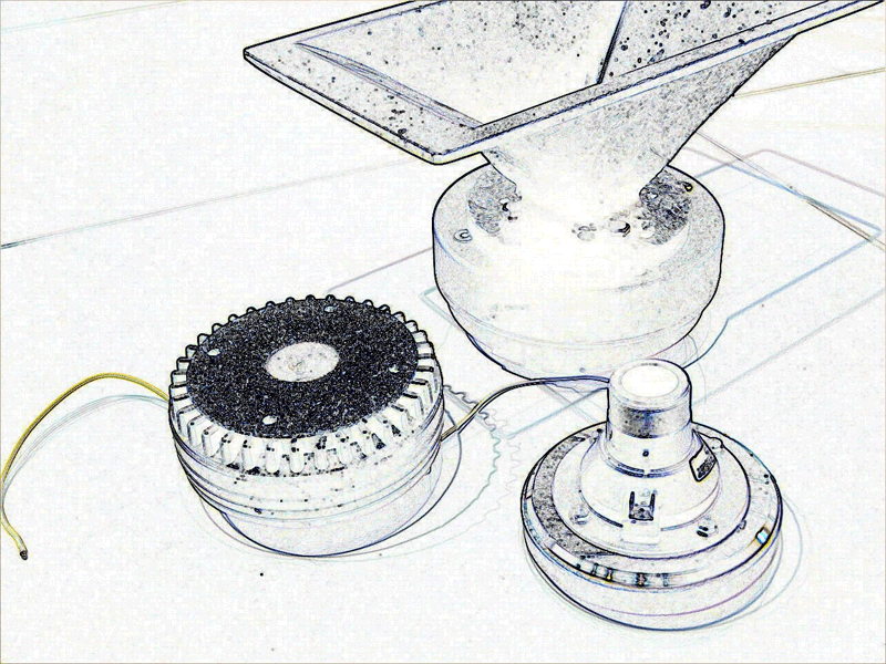
- Tweeter
- Horn compression driver
Applications
- Home
- Automotive
- Multimedia and Professional
Particularities
High-frequency loudspeaker drive units are operated at higher frequencies by using a highpass of a crossover system. Most of the transducers use a moving-coil assembly based on the electro-dynamical transduction principle. At the resonance frequency (about 1 kHz) the radiator (soft or hard dome, diaphragm, membrane) vibrates as a rigid body, and the transfer behavior of the drive unit can be modeled by an equivalent network comprising lumped elements with linear and nonlinear parameters.
The linear parameters comprise the Thiele-Small parameters, visco-elastic parameters (creep factor) and electrical parameters describing the lossy inductance at higher frequencies. The maximal acoustical output is limited by the heating of the coil, regular nonlinearities and irregular defects, such as Rub & Buzz.
Thermal parameters describe the heating of the coil, the heat transfer to the pole tips, magnet and ambience considering conduction and radiation. The dominant nonlinearities are the stiffness Kms(x) or compliance Cms(x) depending on the voice coil displacement x and the resistance Rms(v) varying with velocity v.
This drive unit is usually operated at higher frequencies where bending waves and longitudinal waves are generated on the radiator. Distributed parameters are required to describe the vibration and radiation behavior and can be measured by laser scanning techniques. Modal analysis and other decomposition techniques reveal the modal density, loss factor of the material and radiation problems.
Critical Issues
- Flat SPL response on-axis and off-axis in the far field
- Maximal peak displacement limited by suspension nonlinearities
- Heating of the coil and thermal power handling
- Rocking modes causing voice coil rubbing
- High local displacement on particular points on the diaphragm causing nonlinear distortion
Accessories
Standards
Audio Engineering Society
AES2 Recommended practice Specification of Loudspeaker Components Used in Professional Audio and Sound Reinforcement
AES56 Standard on acoustics – Sound source modelling – Loudspeaker polar radiation measurement
International Electrotechnical Commission
IEC 60268-5 Sound System Equipment, Part 5: Loudspeakers
IEC 62458 Sound System Equipment – Electroacoustic Transducers - Measurement of Large Signal Parameters