Small Signal Lumped Parameters
Characteristics: | KLIPPEL R&D System | KLIPPEL QC System |
|---|---|---|
Resonance frequency fs | LPM, LSI3, PWT, RMA, HMA | IMP, SPL-IMP, MSC |
Mechanical quality factor Qms | LPM, LSI3, PWT, RMA, HMA | IMP, SPL-IMP, MSC |
Electrical quality factor Qes | LPM, LSI3, PWT | IMP, SPL-IMP, MSC |
DC resistance Re | LPM, LSI3, PWT | IMP, SPL-IMP, MSC |
Force factor Bl(x=0) | LPM, LSI3, PWT | IMP, SPL-IMP, TSX |
Mechanical resistance Rms(v=0) | LPM, LSI3, PWT | IMP, SPL-IMP, TSX |
Stiffness Kms(x=0) and compliance Cms(x=0) | LPM, LSI3, PWT | SPL-IMP, TSX |
Additional Thiele-Small parameters (e.g. Vas) | LPM, LSI3, PWT | IMP, SPL-IMP, TSX |
Visco-elastic parameter (creep factor λ) | LPM | TSX |
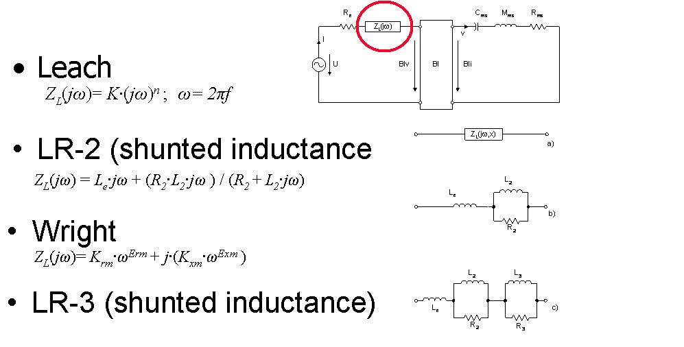
Lossy inductance parameters (Wright, Leach, LR2 model) | LPM | IMP |
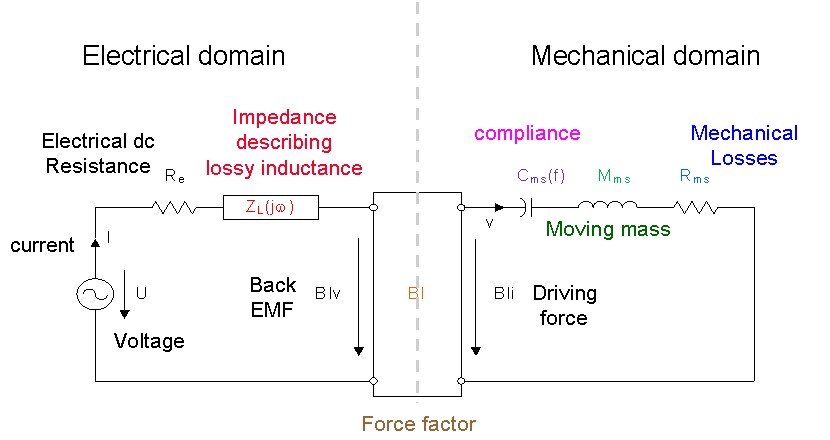
The linear lumped parameters describe the vibration and transfer behavior of the transducer in the small signal domain and at frequencies where the size of the transducer is small compared to the wavelength. An electrical impedance measurement provides the parameters of the electrical equivalent circuit (e.g. dc resistance Re, resonance frequency fs, quality factors Qes, Qms and Qts). Accurate modeling of the impedance at higher frequencies requires additional lumped parameters (e.g. Leach, Wright, LR2 model) describing the electrical losses due to eddy currents in the pole tips.
The mechanical parameters (moving mass Mms) can be estimated by performing a second perturbation measurement (with added mass, in test enclosure). Both methods are not practical on high-frequency transducers. The test enclosure method requires accurate value of the effective radiation area Sd and the air volume. A direct measurement of the mechanical vibration and the use of a laser sensor gives more accurate results, especially if a spatial averaging on the radiators surface compensates for rocking modes. Direct measurement of the mechanical vibration reveals visco-elastic effects (creep) which reduces the stiffness of the suspension at very low frequencies. The particular Thiele-Small parameters (e.g. equivalent air volume of the suspension) can be derived from the physical parameters.
Nonlinear distortion generated by the transducer at higher amplitudes may affect the accuracy of the linear parameters. Novel measurement techniques which are based on a nonlinear loudspeaker model provide the parameter at the rest position x=0 which correspond with small signal parameters. However, due to visco-elastic properties of the suspension material, the stiffness Kms(x=0) and the resonance frequency fs(x=0) decreases with the peak displacement xpeak. The mechanical parameters without air influence can be measured by operating the transducer in vacuum.

KLIPPEL R&D SYSTEM (development)
Module | Comment |
|---|---|
LPM measures the small signal parameters by using a multi-tone stimulus which ensures the best SNR of voltage and current in the small signal domain. LPM supports perturbation and laser techniques, checks linear operation of the transducer and uses extended models for creep and lossy inductance. | |
LSI3 measures the parameter values at the rest position x=0 while exciting the speaker with pink noise of high amplitude. | |
PWT measures the parameter values at the rest position x=0 while operating the transducer in the large signal domain using an arbitrary stimulus (music). | |
SCN measures the mechanical transfer function Hx(f) by spatial averaging of the displacement at multiple points on the radiator to cope with rocking modes. | |
| Higher Modal Analysis (HMA) | HMA performs modal analysis of distributed vibration data (like from Klippel SCN). It decomposes the total vibration into the contribution of separate modes, described by modal parameters (resonance frequency, damping coefficients, gain) and mode-shapes (characteristic vibration patterns). It visualizes cone deformation and simplifies the systematic analysis of mode interaction and sound radiation. |
| Rocking Mode Analysis (RMA) | RMA analyses undesired rocking modes of the diaphragm which can cause impulsive distortion. It determines imbalances in the distributions of mass, stiffness and electromagnetic force factor, the main root causes for rocking motion. It also quantifies the excitation force caused by each of these effects and supports the user to find the location of the disturbance on the diaphragm. |
KLIPPEL QC SYSTEM (end-of-line testing)
Module | Comment |
|---|---|
IMP measures the Thiele/Small and other small signal parameters of the linear transducer model at high speed using a sinusoidal sweep (chirp) or multi-tone stimulus in the small signal domain. | |
| Sound Pressure and Impedance Task (SPL-IMP) | The SPL-IMP is a comprehensive measurement task dedicated to QC applications. It combines the speed and sensitivity of the SPL task with the precise lumped parameter measurement of the Impedance Task. A sine chirp excitation is used. |
MSC dispenses with an additional small signal measurement but measures the nonlinear parameters at the rest position x=0 while operating the transducer in the large signal domain using an ultra-short multi-tone stimulus. | |
| T/S Parameter Laser Fitting (TSX) | The TSX enhances the QC Impedance Task with laser displacement measurement for full mechanical linear parameter identification. |
Example:
Templates of KLIPPEL products
Name of the Template | Application |
|---|---|
LPM Microspeaker T/S (SP2) | Linear parameters of microspeakers using sensitive current sensor 2 |
LPM Subwoofer T/S (Sp1) | Linear parameters of subwoofers using standard current sensor 1 |
LPM Subwoofer T/S (Sp2) | Linear parameters of subwoofers using sensitive current sensor 2 |
LPM Tweeter T/S (SP2) | Linear parameters of tweeters using sensitive current sensor 2 |
LPM Woofer T/S (Sp1) | Linear parameters of woofers using standard current sensor 1 |
LPM Woofer T/S (Sp2) | Linear parameters of woofers using sensitive current sensor 2 |
LPM Woofer T/S added mass | Linear parameters of woofers using added mass method |
LSI Tweeter Nonlin. Para Sp2 | Tweeters with fs > 400 Hz at sensitive current sensor 2 |
LSI Headphone Nonlin. P. Sp2 | Nonlinear parameters of headphones with fs < 300 Hz at sensitive current sensor 2 |
LSI Woofer Nonl. P. Sp1 | Nonlinear parameters of woofers with fs < 300 Hz at standard current sensor 1 |
LSI Woofer Nonl.+Therm. Sp1 | Nonlinear and thermal parameters of woofers with fs < 300 Hz at standard current sensor Sp1 |
LSI Woofer+Box Nonl. P Sp1 | Nonlinear parameters of woofers operated in free air, sealed or vented enclosure with a resonance frequency fs < 300 Hz at standard current sensor Sp1 |
LSI Microspeaker Nonl. P. Sp2 | Nonlinear parameters of microspeakers with fs > 300 Hz at sensitive current sensor 2 |
PWT 8 Woofers Param. ID Noise | Parameter identification of woofers using internal test signal (no cycling, no stepping) |
PWT Woofer Param. ID MUSIC | Parameter Identification of Woofers using external test signal (no ON/OFF cycling, no stepping) |
PWT Woofer param. ID NOISE | Parameter Identification of Woofers using internal test signal (no ON/OFF cycling, no stepping) |
Diagnost. MIDRANGE Sp1 | Comprehensive testing of midrange drivers with a resonance 30 Hz < fs < 200 Hz using standard current sensor 1 |
Diagnost. RUB&BUZZ Sp1 | Batch of Rub & Buzz tests with increased voltage (applied to high power devices) |
Diagnost. RUB & BUZZ Sp2 | Batch of Rub & Buzz tests with increased voltage (applied to low power devices) |
Diagnost. SUBWOOFER (Sp1) | Comprehensive testing of subwoofers with a resonance 10 Hz < fs < 70 Hz using standard current sensor 1 |
Diagnostics MICROSPEAKER Sp2 | Comprehensive testing of microspeakers with a resonance 100 Hz < fs < 2 kHz using sensitive current sensor 2 |
Diagnostics TWEETER (Sp2) | Comprehensive testing of tweeters with a resonance 100 Hz < fs < 2 kHz using sensitive current sensor 2 |
Diagnostics VENTED BOX SP1 | Comprehensive testing of vented box systems using standard current sensor 1 |
Diagnostics WOOFER (Sp1) | Comprehensive testing of subwoofers with a resonance 30 Hz < fs < 200 Hz using standard current sensor 1 |
Diagnostics WOOFER Sp1,2 | Comprehensive testing of subwoofers with a resonance 30 Hz < fs < 200 Hz using current sensor 1 and 2 |
Application Notes
Standards
Audio Engineering Society
AES2 Recommended practice Specification of Loudspeaker Components Used in Professional Audio and Sound Reinforcement
International Electrotechnical Commission
IEC Standard IEC 60268-5 Sound System Equipment, Part 5: Loudspeakers
IEC Standard IEC 62458 Sound System Equipment – Electroacoustic Transducers - Measurement of Large Signal Parameters
Other Related Tests
Typical Test Objects
Papers and Preprints
W. Klippel, U. Seidel, “Fast and Accurate Measurement of Linear Transducer Parameters,” presented at the 110th Convention of the Audio Eng. Soc., Amsterdam, May 12-15, 2001, Preprint 5308, J. of Audio Eng. Soc., Volume 49, No. 6, 2001 June, P. 526. (abstract)
M. H. Knudsen, et al., “Low-Frequency Loudspeaker Models that Include Suspension Creep,” J. of Audio Eng. Soc., Volume 41, pp. 3-18, (Jan./Feb. 1993).
M. Zollner, E. Zwicker, „Elektroakustik,“ Springer Verlag, 2003.
L. L. Beranek, “Acoustics”, McGraw-Hill, New York 1965.
D. Clark, “Precision Measurement of Loudspeaker Parameters,“ J. of Audio Eng. Soc., Volume 45, pp. 129 – 140, (1997 March).
R. H. Small, “Direct-Radiator Loudspeaker System Analysis,“ J. of Audio Eng. Soc., Volume 20, pp. 383 – 395 (1972 June).
R. H. Small, “Closed-Box Loudspeaker Systems, Part I: Analysis,” J. Audio Eng. Soc., Volume 20, pp. 798 – 808 (1972 Dec.).
A. N. Thiele, “Loudspeakers in Vented Boxes: Part I and II,” in Loudspeakers, Volume 1 (Audio Eng. Soc., New York, 1978).
J. Vanderkooy, “A Model of Loudspeaker Driver Impedance Incorporating Eddy Currents in the Pole Structure,” J. of Audio Eng. Soc., Volume 37, No. 3, pp. 119-128, March 1989.
W. M. Leach, “Loudspeaker Voice-Coil Inductance Losses: Circuit Models, Parameter Estimation, and Effect on Frequency Response,“ J. of Audio Eng. Soc., Volume 50, No. 6, pp. 442-450, June 2002.
J. R. Wright, “An Empirical Model for Loudspeaker Motor Impedance,“ J. of Audio Eng. Soc., Volume 38, No. 10, pp. 749-754, October 1990.
M. Dodd, et al., “Voice Coil Impedance as a Function of Frequency and Displacement,” presented at the 117th Convention of the Audio Eng. Soc., 2004 October 28–31, San Francisco, CA, USA.


