Voice Coil Temperature
Characteristics: | KLIPPEL R&D System |
|---|---|
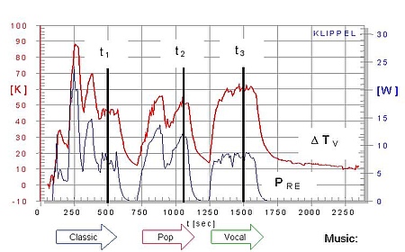
Variation of dc resistance Re versus time | LSI3, PWT, LAA |
Increase of voice coil temperature ΔTv | LSI3, PWT, DIS, LAA, MTON |
Heating and cooling curves | LSI3, PWT |
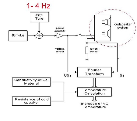
The voice coil temperature can be monitored without using an additional sensor by measuring the dc resistance and considering the material properties of the voice coil. The dc resistance corresponds with the electrical impedance at very low frequencies. An additional pilot tone (1 – 4 Hz) has to be added to the stimulus (test signal or audio signal) to ensure a reliable measurement of the dc resistance which is not affected by the motional impedance and inductance of the coil. The short thermal time constants in small transducers (microspeaker, tweeter) require a fast method and dedicated signal processing to measure the dc resistance as fast as possible.
KLIPPEL R&D SYSTEM (development)
Module | Comment |
|---|---|
LSI3 measures the resistance of the cold transducer at very low frequencies at the beginning of the measurement. This value is used as a reference for calculating the increase of the voice coil temperature during the following identification process. | |
PWT adds a pilot tone of 1 - 4 Hz of low amplitude to the excitation signal generated by the internal generator or to the external audio signal. Thus, the temperature can also be measured during an off-cycle when no regular stimulus is supplied to speaker. The power test provides an ultra-fast sampling of the voice coil temperature (100 ms) to measure the temperature variation at high temporal resolution. | |
DIS provides a special measurement (pilot tone at 375 / 750 / 2250 Hz) which estimates the voice coil temperature at sufficient accuracy to protect the transducer under test. | |
| Live Audio Analyzer (LAA) | LAA measures the DC resistance of a transducer by adding a pilot tone of low amplitude to the excitation signal. The pilot tone is added to the signal provided by the computer, thus temperature measurement during off-cycles is supported. For external signals, the user may specify a single tracking frequency, or uses a whole tracking band with sufficient excitation. |
| Multi-Tone Measurement (MTON) | MTON measures the DC resistance of the DUT to monitor the increase of voice coil temperature by adding a low-frequency pilot tone to the multi-tone stimulus. |
Templates of KLIPPEL products
Name of the Template | Application |
|---|---|
Thermal Parameters (woofer) | Analysis of heat transfer in woofers based on identified thermal woofer parameters |
Thermal Parameters AN 18 | Thermal Parameters measured by using PWT module according Application Note 18 |
Thermal Parameters AN 19 | Thermal Parameters measured by using PWT module according Application Note 19 |
LSI Woofer Nonl.+Therm. Sp1 | Nonlinear and thermal parameters of woofers with fs < 300 Hz at standard current sensor Sp1 |
LSI Woofer+Box Nonl. P Sp1 | Nonlinear parameters of woofers operated in free air, sealed or vented enclosure with a resonance frequency fs < 300 Hz at standard current sensor Sp1 |
DIS Compression Out(in) | Output amplitude versus input amplitude at four frequencies |
DIS Harmonics vs. Voltage | Harmonic distortion measurement versus amplitude |
DIS SPL, Harm protected | Harmonic distortion measurement with protection |
SIM Compression Out(In) | Output amplitude versus input amplitude at four frequencies using large signal parameters imported from LSI; Simulated results are comparable with DIS Compression Out(In). |
SIM Therm. Analysis (1 tone) | Heat transfer based on thermal parameters imported from LSI using a single-tone stimulus |
SIM Therm. Analysis (2 tone) | Heat transfer based on thermal parameters imported from LSI using a two-tone stimulus |
PWT 8 Woofers Param. ID Noise | Parameter identification of woofers using internal test signal (no cycling, no stepping) |
PWT EIA accelerated life test | Accelerated life testing according EIA 426 B A. 4 using any external signal to monitor temperature, power and resistance |
PWT IEC Long term Voltage | Power test to determine long-term maximal voltage according IEC 60268-5 paragraph 17.3 without parameter measurement for one device monitoring voltage, resistance, temperature and power |
PWT IEC Short term Voltage | Power test to determine short term maximal voltage according IEC 60268-5 paragraph 17.2 without parameter measurement applied to 1 DUT monitoring temperature, power and resistance |
PWT Powtest (fast Temp.) | Power test for fast monitoring of temperature, power and resistance without parameter measurement using external continuous signal (noise) supplied to IN1 |
PWT Powtest EXT. GENER. | Power test for monitoring temperature, power and resistance using external continuous signal (noise) supplied to IN1 |
PWT Powtest LIMITS | Power test to find maximal input voltage, power and temperature limits without parameter measurement applied to 1 DUT |
PWT Powtest MUSIC | Power test without parameter measurement monitoring temperature, power, voltage and resistance using any external signal |
PWT Powtest SWEEP | Power test for measuring the thermal time constant of the voice coil using sweep signal with low crest factor |
PWT Powtest TIME Const. | Power test for measuring time constant of voice coil using internal test signal with cycling (ON/OFF phase) |
PWT Woofer Param. ID MUSIC | Parameter Identification of Woofers using external test signal (no ON/OFF cycling, no stepping) |
PWT Woofer param. ID NOISE | Parameter Identification of Woofers using internal test signal (no ON/OFF cycling, no stepping) |
Standards
Audio Engineering Society
AES2 Recommended practice Specification of Loudspeaker Components Used in Professional Audio and Sound Reinforcement
Consumer Electronics Association
CEA-426-B Loudspeakers, Optimum Amplifier Power
European Telecommunications Standards Institute
EIA 426B Loudspeaker Power Rating Test CD provided by ALMA International
International Electrotechnical Commission
IEC 60268-5 Sound System Equipment, Part 5: Loudspeakers
Other Related Tests
Typical Test Objects
Papers and Preprints
Y. Shen, “Accelerated Power Test Analysis Based on Loudspeaker Life Distribution,” presented at the 124th Convention of Audio Eng. Soc., May 2008, Preprint 7345.
W. Klippel, “Nonlinear Modeling of the Heat Transfer in Loudspeakers,” J. of Audio Eng. Soc. 52, Volume 1, 2004 January.
C. Zuccatti, “Thermal Parameters and Power Ratings of Loudspeakers,” J. of Audio Eng. Soc., Volume 38, No. 1, 2, 1990 January/February.
K. M. Pedersen, “Thermal Overload Protection of High Frequency Loudspeakers,” Report of Final Year Dissertation at Salford University.
Henricksen, “Heat Transfer Mechanisms in Loudspeakers: Analysis, Measurement and Design,” J. of Audio Eng. Soc., Volume 35, No. 10, 1987 October.


